Author: Nguyen Ngoc Thanh – Nguyen ThoiTrung – Vo Ba Khanh Trinh
Email: Nguyenngocthanh209@gmail.com - Thoitrung88@gmail.com – vobakhanhtrinh@gmail.com
Introduction:
Model is designed to simulate the operation of the engine control system. It consists of engine, sensors, actuators, fault simulator and engine control unit. The engine control unit(ECU) is the central control element for an engine. The ECU obtains all the necessary information by means of sensors( Intake air, temperature, knock…). It utilises the IPO model (input-process-output) to assess incoming data and then send out signals to operate the appropriate actuators. It is essential for students to understand not only individual components but also the complex control loops, diagnostic system and so on…
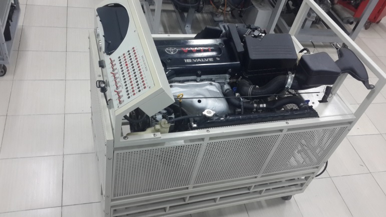
Fig 1. Engine management trainer
Specifications:
- External size (LxWxH) : 1350mm x 800mm x 1240mm
- Immobilizer
- 16-pin OBD diagnostic plug, OBD II standard.
- Electronically controlled fuel injection system
- Cylinder specific anti-knock control .
- Direct ignition system.
- Fault simulation.
- Electronic pedal control (EPC) accelerator pedal sensor.
- Power : 12V DC
Reference:
1. Toyota Motor USA, Overview of OBD and Regulations
2. Ralph Birnbaum and G Jerry Truglia, Getting to know OBD II, Second edition, 2004
3. Toyota EFI #2, Air induction system.
4. Alan W. M. Bonnick, Automotive computer controlled systems, 2001
5. Toyota Technical training, Introduction to enging control system, section 1
 Vietnamese
